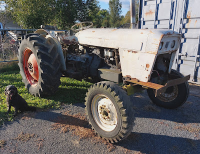
Can we make it an eTractor? Yes, we can (well, we will see 😃)
After completing other electric scooter projects (see Electric Joker)
I wanted to do something more challenging. Thought about converting a
car, but there's way too many requirements to complete a road legal
conversion. So, why not a tractor for use on our lifestyle block?
Why did I choose a David Brown tractor for my Electric Tractor project? Mainly because I wanted a tractor that didn't rely on the petrol/diesel engine (ICE - internal combustion engine) to connect the front frame and wheels to the rest of the tractor. Looked around for a few potential options - Fergies and Fords were out, but David Browns seemed like a good option.
Looking at the David Brown 880 my initial plan (Plan A) was:
The David Brown 880 picture below shows you the tractor and how the major engine and transmission components are laid out.

And, the following gives an exploded view of those major components:


My plan was to remove the engine - basically everything above the sump
frame including the crankshaft. The sump frame will remain, as it
provides the structure for the front frame (and front axles and wheels)
to stay connected with the rest of the tractor. Although the sump frame
may need some reinforcing, which I'll hopefully be able to do when
mounting the electric motor and structures for holding batteries.


The flywheel and double-clutch, one for PTO and one for transmission,
will remain (NB. the orientation of the double-clutch diagram above is
180deg out - i.e. the PTO friction plate end goes into the right-hand
side of the flywheel in the left diagram). So, the electric motor would
be attached to the flywheel - I will need to get a coupling manufactured
to match how the crankshaft was bolted to the flywheel.
However, as the engine normally runs from 700 to 2000rpm, I expect a
reduction gearbox, or pulleys and belt, will need to be used between the
electric motor and the flywheel. Plus the reduction
box/pulleys-&-belt will also allow the motor to be mounted above the
sump frame, as I don't expect there will be enough room down in the
sump frame where the coupling will attach to the flywheel.
So, that was the plan anyway... however, now see Plan B

Comments
Post a Comment